H5007 Performance Data DataCom Products Group Hank Hinrichs, Principal Engineer U.S.: 858 674 8100 * U.K.: 44 1483 401700 * France: 33 3 84 35 04 04 * Singapore: 65 287 8998 * Taiwan: 886 2 26980228 * http://www.pulseeng.com G021.B (2/00) H5007 Performance Data The following graphs typify the scattering (both balanced and unbalanced) and impedance parameters of the H5007, a magnetic transceiver for long haul gigabit (802.3ab) applications. The H5007 is designed around a 10/100/1000Base-T compliant transformer, having a 1:1 turns ratio and includes both series and shunt chokes for common mode signal suppression. S-parameter measurements were taken using a HP8751A network analyzer connected to a HP4380A cable analyzer and includes S11 and S22, attenuation and phase response for S12 and S21, differential to common mode rejection, common to common mode rejection ratio, and common to differential mode rejection. Z-parameter measurements were taken using a HP4396A
 16 Pages, 158 KB, Original
91N01NUX ORIENT TCC0 HOST I/F TCC1 GND GND Product structure: Silicon integrated circuit www.rohm.com (c) 2019 ROHM Co., Ltd. All rights reserved. TSZ22111 * 14 * 001 GND This product has no designed protection against radioactive rays. 1/18 TSZ02201-0232AH500730-1-2 07.Jun.2019 Rev.001 BD91N01NUX Contents General Description ................................................................................................................................................................ 1 Features ................................................................................................................................................................................. 1 Applications ............................................................................................................................................................................ 1 Key Specifications ............................................................................................................................
 21 Pages, 1450 KB, Original
 One part is identified in this cross reference. Multiple parts with different platforms can be found on the referenced data sheet. C. For detailed information about this series, e-mail: prodinfo_lan@pulseeng.com or call Pulse and ask for LAN Applications H5007 H5062 H5007 H5062 H5077 H5007 H5062 H5004 H6062 H5007 H5062 H5004 H5077 H6062 Single Dual Part Data Part Data Number Sheet Number Sheet A DISCRETE COMPONENTS & INTEGRATED MODULES LAN GIGABIT IC CROSS REFERENCE 1xN Part Data Number Sheet JC0 Series 4, C J405* JC0 Series 4, C J405* JC0 Series 4, C J405* JW0 Series D JW0 Series D JW0 Series D SMT - Surface Mount Package THT - Through Hole Package NOTE: Most Pulse products can be manufactured to comply with the RoHS (Restriction of Hazardous Substances) directive. These parts are identified by adding the suffix "NL" at the end of the part number. J408 J408 J408 J408 RJ45/USB Part Data Number Sheet JC0 Series 4, C J405* JW0 Series D 2xN Part Data Number Sh
 12 Pages, 255 KB, Original
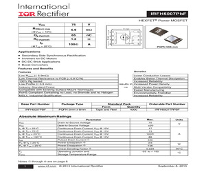
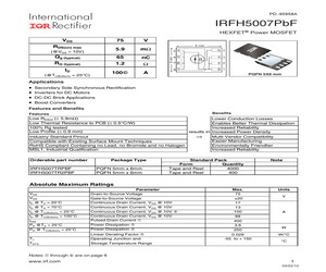
H5007PbF HEXFET(R) Power MOSFET VDS 75 V R DS(on) max 5.9 m Qg (typical) 65 nC RG (typical) 1.2 (@V GS = 10V) ID (@Tmb = 25C) h 100 A PQFN 5X6 mm Applications * * * * Secondary Side Synchronous Rectification Inverters for DC Motors DC-DC Brick Applications Boost Converters Features and Benefits Benefits Features Low RDSon ( 5.9m) Low Thermal Resistance to PCB ( 0.8C/W) 100% Rg tested Low Profile ( 0.9 mm) Lower Conduction Losses Enables Better Thermal Dissipation Increased Reliability results in Increased Power Density Industry-Standard Pinout Compatible with Existing Surface Mount Techniques RoHS Compliant Containing no Lead, no Bromide and no Halogen MSL1, Industrial Qualification Base Part Number Package Type IRFH5007PBF PQFN 5mm x 6mm Multi-Vendor Compatibility Easier Manufacturing Environmentally Friendlier Increased Reliability Standard Pack Form Quantity Tape and Reel 4000 Orderable Part Number IRFH5007TRPBF Absolute Maximum Ratings Max. Units VDS VGS Drain-to-Sou
 10 Pages, 284 KB, Original
H5007PbF HEXFET(R) Power MOSFET VDS 75 V R DS(on) max 5.9 m Qg (typical) 65 nC RG (typical) 1.2 (@V GS = 10V) h ID 100 (@Tmb = 25C) A PQFN 5X6 mm Applications * * * * Secondary Side Synchronous Rectification Inverters for DC Motors DC-DC Brick Applications Boost Converters Features and Benefits Benefits Features Low RDSon ( 5.9m) Low Thermal Resistance to PCB ( 0.8C/W) 100% Rg tested Low Profile ( 0.9 mm) Lower Conduction Losses Enables Better Thermal Dissipation Increased Reliability results in Increased Power Density Industry-Standard Pinout Compatible with Existing Surface Mount Techniques RoHS Compliant Containing no Lead, no Bromide and no Halogen MSL1, Industrial Qualification Base Part Number Package Type IRFH5007PBF PQFN 5mm x 6mm Multi-Vendor Compatibility Easier Manufacturing Environmentally Friendlier Increased Reliability Standard Pack Form Quantity Tape and Reel 4000 Orderable Part Number IRFH5007TRPBF Absolute Maximum Ratings Max. Units VDS VGS Drain-to-Sou
 8 Pages, 250 KB, Original
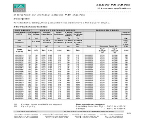
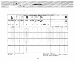
M A IF = 20 mA Rth Pdiss f = 1 MHz f = 120 MHz IR = 6 mA VR = 10 V 1W 50 TYPE Case m V typ. min pF typ. max ns ns max typ. typ. F 27 d TYPE STANDARD CASES (1) C2a (1) EH50033 EH50034 EH50035 EH50036 EH50037 EH50052 EH50053 EH50054 EH50055 EH50056 EH50057 EH50071 EH50072 EH50073 EH50074 EH50075 EH50076 EH50077 EH50101 EH50102 EH50103 EH50104 EH50105 EH50106 EH50107 (1) (2) 25 30 35 55 65 30 35 40 50 65 80 35 40 45 50 60 80 100 45 50 60 70 90 110 130 30 30 30 30 30 50 50 50 50 50 50 70 70 70 70 70 70 70 100 100 100 100 100 100 100 0.08 0.12 0.17 0.23 0.40 0.06 0.08 0.12 0.17 0.23 0.40 0.04 0.06 0.08 0.12 0.17 0.23 0.40 0.04 0.06 0.08 0.12 0.17 0.23 0.40 0.12 0.17 0.23 0.40 0.60 0.08 0.12 0.17 0.23 0.40 0.60 0.06 0.08 0.12 0.17 0.23 0.40 0.60 0.06 0.08 0.12 0.17 0.23 0.40 0.60 1.8 1.5 1.0 0.9 0.7 1.6 1.4 1.1 1.0 0.9 0.7 2.0 1.7 1.6 1.4 1.0 0.9 0.7 1.9 1.7 1.4 1.2 1.0 0.8 0.6 20 20 25 30 40 30 30 35 40 50 60 50 50 60 60 100
 1 Pages, 25 KB, Original
 10 mA IF = 10 MA IF = 20 mA Rth Pdiss f = 1 MHz f = 120 MHz IR = 6 mA VR = 10 V 1W TCR 50 Type Case m V typ. min. pF typ. max ns ns max typ. typ. F 27 d Type C2a (1) EH50033 EH50034 EH50035 EH50036 EH50037 EH50052 EH50053 EH50054 EH50055 EH50056 EH50057 EH50071 EH50072 EH50073 EH50074 EH50075 EH50076 EH50077 EH50101 EH50102 EH50103 EH50104 EH50105 EH50106 EH50107 (1) (2) 25 30 35 55 65 30 35 40 50 65 80 35 40 45 50 60 80 100 45 50 60 70 90 110 130 30 30 30 30 30 50 50 50 50 50 50 70 70 70 70 70 70 70 100 100 100 100 100 100 100 0.08 0.12 0.17 0.23 0.40 0.06 0.08 0.12 0.17 0.23 0.40 0.04 0.06 0.08 0.12 0.17 0.23 0.40 0.04 0.06 0.08 0.12 0.17 0.23 0.40 0.12 0.17 0.23 0.40 0.60 0.08 0.12 0.17 0.23 0.40 0.60 0.06 0.08 0.12 0.17 0.23 0.40 0.60 0.06 0.08 0.12 0.17 0.23 0.40 0.60 1.8 1.5 1.0 0.9 0.7 1.6 1.4 1.1 1.0 0.9 0.7 2.0 1.7 1.6 1.4 1.0 0.9 0.7 1.9 1.7 1.4 1.2 1.0 0.8 0.6 Custom cases available on request C T = Cj + C b
 56 Pages, 510 KB, Original
 10 mA IF = 10 MA IF = 20 mA Rth Pdiss f = 1 MHz f = 120 MHz IR = 6 mA VR = 10 V 1W TCR 50 Type Case m V typ. min. pF typ. max ns ns max typ. typ. F 27 d Type C2a (1) EH50033 EH50034 EH50035 EH50036 EH50037 EH50052 EH50053 EH50054 EH50055 EH50056 EH50057 EH50071 EH50072 EH50073 EH50074 EH50075 EH50076 EH50077 EH50101 EH50102 EH50103 EH50104 EH50105 EH50106 EH50107 (1) (2) 25 30 35 55 65 30 35 40 50 65 80 35 40 45 50 60 80 100 45 50 60 70 90 110 130 30 30 30 30 30 50 50 50 50 50 50 70 70 70 70 70 70 70 100 100 100 100 100 100 100 0.08 0.12 0.17 0.23 0.40 0.06 0.08 0.12 0.17 0.23 0.40 0.04 0.06 0.08 0.12 0.17 0.23 0.40 0.04 0.06 0.08 0.12 0.17 0.23 0.40 0.12 0.17 0.23 0.40 0.60 0.08 0.12 0.17 0.23 0.40 0.60 0.06 0.08 0.12 0.17 0.23 0.40 0.60 0.06 0.08 0.12 0.17 0.23 0.40 0.60 1.8 1.5 1.0 0.9 0.7 1.6 1.4 1.1 1.0 0.9 0.7 2.0 1.7 1.6 1.4 1.0 0.9 0.7 1.9 1.7 1.4 1.2 1.0 0.8 0.6 Custom cases available on request C T = Cj + C b
 1 Pages, 15 KB, Original
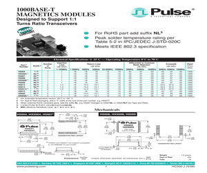
t 1:1 Turns Ratio Transceivers For RoHS part add suffix NL3 Peak solder temperature rating per Table 5-2 in IPC/JEDEC J-STD-020C Meets IEEE 802.3 specification Electrical Specifications @ 25C -- Operating Temperature 0C to 70C Part 2 Number H5004 HX5004 1 H5007 H5008 HX5008 1 H5009 H5012 H5014 HX5014 1 H5015 H5020 HX5020 1 1. 2 3. 4. 5. RoHS 3 Number of Ports 4, 5c 1 1 1 1 1 1 2 2 2 1 2 2 NL5c NL5c NL5c NL5a NL5a NL5a NL5a 4, 5a NL5a NL5c 4, 5c Insertion Loss (dB MAX) 1-100MHz 1 1 1 1 1 1 1.4 1.4 1.4 1 1 1 Return Loss (dB MIN) 1-30MHz 40MHz -18 -18 -18 -18 -18 -18 -18 -18 -18 -18 -18 -18 -16 -14.4 -16 -14.4 -16 -14.4 -18 -18 -18 -14.4 -18 -14.4 50MHz 60-80MHz 100MHz -16 -12 -10 -16 -12 -10 -16 -12 -10 -16 -12 -10 -16 -12 -10 -16 -12 -10 -13.1 -12 -10 -13.1 -12 -10 -13.1 -12 -10 -16 -12 -10 -13.1 -12 -10 -13.1 -12 -10 Differential to Common Crosstalk Hipot Mode Rejection (VRMS (dB MIN) (dB MIN) MIN) 30MHz 60MHz 100MHz 30MHz 60MHz 100MHz -43 -37 -33 -43 -37 -33 1500 -43 -37 -33 -43 -37 -33 1500 -43
 4 Pages, 191 KB, Original
H5007PbF HEXFET(R) Power MOSFET VDS 75 V R DS(on) max 5.9 m Qg (typical) 65 nC RG (typical) 1.2 (@V GS = 10V) ID (@Tmb = 25C) h 100 A PQFN 5X6 mm Applications * * * * Secondary Side Synchronous Rectification Inverters for DC Motors DC-DC Brick Applications Boost Converters Features and Benefits Benefits Features Low RDSon ( 5.9m) Low Thermal Resistance to PCB ( 0.8C/W) 100% Rg tested Low Profile ( 0.9 mm) Lower Conduction Losses Enables Better Thermal Dissipation Increased Reliability results in Increased Power Density Industry-Standard Pinout Compatible with Existing Surface Mount Techniques RoHS Compliant Containing no Lead, no Bromide and no Halogen MSL1, Industrial Qualification Base Part Number Package Type IRFH5007PBF PQFN 5mm x 6mm Multi-Vendor Compatibility Easier Manufacturing Environmentally Friendlier Increased Reliability Standard Pack Form Quantity Tape and Reel 4000 Orderable Part Number IRFH5007TRPBF Absolute Maximum Ratings Max. Units VDS VGS Drain-to-Sou
 10 Pages, 270 KB, Original
H5007PbF HEXFET(R) Power MOSFET VDS 75 V R DS(on) max 5.9 m Qg (typical) 65 nC RG (typical) 1.2 (@V GS = 10V) ID (@Tmb = 25C) h 100 A PQFN 5X6 mm Applications * * * * Secondary Side Synchronous Rectification Inverters for DC Motors DC-DC Brick Applications Boost Converters Features and Benefits Benefits Features Low RDSon ( 5.9m) Low Thermal Resistance to PCB ( 0.8C/W) 100% Rg tested Low Profile ( 0.9 mm) Lower Conduction Losses Enables Better Thermal Dissipation Increased Reliability results in Increased Power Density Industry-Standard Pinout Compatible with Existing Surface Mount Techniques RoHS Compliant Containing no Lead, no Bromide and no Halogen MSL1, Industrial Qualification Base Part Number Package Type IRFH5007PBF PQFN 5mm x 6mm Multi-Vendor Compatibility Easier Manufacturing Environmentally Friendlier Increased Reliability Standard Pack Form Quantity Tape and Reel 4000 Orderable Part Number IRFH5007TRPBF Absolute Maximum Ratings Max. Units VDS VGS Drain-to-Sou
 9 Pages, 265 KB, Original
g options, from through hole SIL devices to the smallest available surface mount solution at .078" (1,98 mm). LAN MODULES IC CROSS REFERENCE IC CROSS REFERENCE: GIGABIT TECHNOLOGY IC Manufacturer Broadcom IC Part No. Pulse Part No. Ports Supported BCM5400 H5007 Single Port H5004 Single Port BCM5401 H5007 Single Port H5008 Single Port Intel (Level One) LXT1000 H5007 Single Port Lucent LU8X31 H5007 Single Port LU8X32 H5007 Single Port LU8X24FT H5008 Single Port Marvell 88E1000 H5007 Single Port Semiconductor H5008 Single Port 88E1010 H5007 Single Port H5008 Single Port 88E1020 H5007 Single Port H5008 Single Port National DP83891 H5007 Single Port Semiconductor H5004 Single Port DP83861 H5007 Single Port H5008 Single Port DP83862 H5007 Single Port 1. T = Transformer, C = Chokes, S = Shunt Inductor 2. SOIC = 50 mil pitch leads, SMT - 100 ml pitch leads (Surface Mount) Pack
 3 Pages, 37 KB, Original
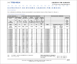
DH50054| F27d | M208 | A22e 60 EH 50055] 50 50 1017 | 023 1.0 40 4.0 DH50055' F27d | M208 | A22e 50 EH 531/EH 50056] 65 50 0.23 | 0.40 0.9 50 5.0 ]DH531/DH50056| F27d | M208 | Az2e 45 EH 50057] 80 50 | 0.40 | 0.60 08 60 6.0 DH50057) F27d | M208 | A22e 45 EH50071| 35 70 | 0.04 | 0.06 2.0 40 40 DH50071) F27d | M208 | A22e 70 EH50072| 40 70 | 0.06 | 0.08 1.8 40 40 DH 50072} F27d | M208 | A22e 70 EH50073) 45 70 | 0.08 | 0.12 16 50; 5.0 DH50073} F27d | M208 | A22e 60 'EH50074, 50 70/012 | 0.17 14 60 6.0 DH50074) F27d | M208 | A22e 50 EH 50075) 60 70 | 0.17 | 0.23 11 70 7.0 DH50075| F27d | M208 | Ae 45 EH 532/EH 50076] 80 70 023 | 0.40 1.0 80 8.0 |DH532/DH50076| F27d | M208 | A22e 40 EH50077/ 100 70 | 040 | 0.60 0.9 90 90 DH50077) F27d | M208 | A22e 40 EHS0101| 45 100 | 0.04 | 0.08 24 60 6.0 DH50101/ F27d | M208 | A22e 60 FH50102) 50 100 | 0.06 | 0.08 19 70 7.0 DH50102| F27d
 1 Pages, 239 KB, Scan
H5007EFNL DATE CODE CTRY MFG 2. HEADER: DAP (DIALLYL PHTHALATE) WITH FLAMMABILITY RATING UL 94V0O OR BETTER. e 3. STORAGE TEMPERATURE: -20C TO +1250 0 er 4. COMPLIANCE TO J-STD: A. J-STD-002: SOLDERABILITY AT 245C REFLOW PROFILE B. J-STD-020: LEVEL 1, NO MOISTURE SENSITIVE C. J-STD-075: R7, 245C MAXIMUM THROUGH REFLOW SOLDER UUYUUUUUUEUUoUY 5. TO ORDER TAPE & REEL PACKAGING ADD A "T SUFFIX TO THE PART NUMBER(i.e H5007EFNL BECOMES H5007EFNL1T). FINAL OUTLINE @ Copyright, 2014. Pulse Electronics Corp. All rights reserved. Pulse confidential & proprietary. (06/30/14) PRODUCT DESCRIPTION TLA DRAWING PS DRAWING SHEET PART NO. DATASHEET REV. MDL,SIN,1GD,1:1,SM,TU H5007EFNL11 PS2597.001C 1 OF 3 H5007EFNL A EMAIL: PRODINFONETWORK@PULSEELECTRONICS.COM(US). ASIA@PUI SFFI FCTRONICS.COM(Asia) PHONE: USA:858 674 8100, GERMANY:49 7032 78060, SINGAPORE:65 6287 8998, SHANGHAI:86 21 62787060, TAIWAN:886 3 4356768 a Pulse COMPTIANT www.pulseelectronics.com CHANNE
 3 Pages, 474 KB, Scan
H5007PbF HEXFET(R) Power MOSFET VDS RDS(on) max (@VGS = 10V) Qg (typical) RG (typical) ID 75 V 5.9 m 65 nC 1.2 100 (@Tc(Bottom) = 25C) h A PQFN 5X6 mm Applications * * * * Secondary Side Synchronous Rectification Inverters for DC Motors DC-DC Brick Applications Boost Converters Features and Benefits Features Benefits Low RDSon ( 5.9m) Low Thermal Resistance to PCB ( 0.5C/W) 100% Rg tested Low Profile ( 0.9 mm) results in Industry-Standard Pinout Compatible with Existing Surface Mount Techniques RoHS Compliant Containing no Lead, no Bromide and no Halogen MSL1, Industrial Qualification Lower Conduction Losses Enables Better Thermal Dissipation Increased Reliability Increased Power Density Multi-Vendor Compatibility Easier Manufacturing Environmentally Friendlier Increased Reliability Orderable part number IRFH5007TRPBF IRFH5007TR2PBF Package Type PQFN 5mm x 6mm PQFN 5mm x 6mm Standard Pack Form Quantity Tape and Reel 4000 Tape and Reel 400 Note Absolute Maximum Ratings VD
 8 Pages, 212 KB, Original


